The regular price is the current manufacturer's recommended price! FREE shipping for orders over EUR 41,67 (PPLparcel)
Category
    Brands
      Blog
        Products
          No products found
          User

          Improvement in drill-bits

          Improvement in drill-bits
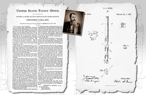
          Specication forming part of Letters Patent No. 38,119, dated April 7, 1863.

          To all whom. it may concern.-
          Be it known that I, STEPHEN AMBRosE MORSE, of East Bridgewater, in the county of Plymouth and State of Massachusetts, have invented `a new and useful Improvement in Drills 5 and I do hereby declare that the following is a full and exact description of the construction and use of the same, reference being had to the accompanying drawings, and to the letters and figures marked thereon.
          Figure I is a front view of the drill. Fig. II is a View of the end of the drill. Fig. III is a section on the line A B, Fig. I. Fig. IV is a section of one of the grooves on the line C D, Fig. l. Fig. V shows the shape of the bottom of the drill.
          The object of my improvement in twist drills is to secure a sharp and straight cutting-edge, presented to the me'tal at a suitable angle and having such a form of the groove, when seen in cross section, as will produce the straight cutting-edge when the drill is ground at the ordinary angle.
          The common drill scrapes the metal that is to be drilled, while my drill cuts the metal and discharges the chips and borings without clogging.
          l'he drill is made, by the use of revolving cutters or burrs, from a solid cylindrical rod, E F G, Fig. I, and when in use is held by the upper part, E F. Thclower part, F G, hasa double spiral groove, P H, cut upon it, the
          Vgeneral appearance of which resembles those in common use, but the difference consists in this, that the section of the groove at any point throughout its length, as at G D, is nearly of the form shown in Fig. IV, the right side ofthe groove being a short, quick curve, and nearly in the direction of the radius, while the left or Vopposite side of the groove is a longer or more shallow curve. The form of the end of the drill when ground is shown in Fig. II, the direction of the cutting edges or lips being shown by the parallel lines I Q. In Fig. V the cutting-edges of the double groove are represented at J and J The periphery on opposite sides of the drill is seen at K K', while the curves L L are of such a shape as to allow as large a mass of metal as possible in the direction of the dotted lines S J and S J for the purpose of giving a strong support to the cutting-edges which revolve in the direction of the arrow.
          When the drill is ground, which should be at about the angle represented in Fig. I, the cutting-edges J J form nearly a straightline, and just back of the edge the curvature of the grooves F and H is such as to form an acute angle, instead of a right angle, as in the common twist-drill. The peculiar shape of the groove is retained throughout its whole length, and as the drill is gradually shortened by grinding the shape of the cutting-edge remains unchanged.
          From the above description it will be perceived that I have produced a twistdrill, having an acutefangled edge extending in the direction of the radius and strengthened by the mass of metal in the rear of the edge or lip.
          I make the spiral grooves with an increasing twistthat is to say, the distance from one spiral to another in the direction of the axis is greater at the upper part of the drill than it is near the point, as shown in Fig. I, the space between the lines O and N being greater than it is between N and M. This increasing twist enla-rges the space in which the borings are received, and they traverse the groove more nearly in aline with the axis, and consequently with less friction.
          A drill made in the manner herein described will make a perfectly straighthole. It willnot diverge from its course while passing through blow holes or soft and hard places. The edge actually cuts the metal, thus diminishing the friction and wear of the edge. The borings or chips are discharged freely, and the edge is strongest at the periphery, where the strain is greatest.
          What I claim, and' desire to secure by Letters Patent, is
          1. A twistdrill, in which the spiral grooves are so cut or formed that the curvature of that side of the groove which makes the cuttinged ge is very nearly in the direction ot the radius, and when the drill is ground at the ordinary angle presents a straight and acuteangled edge or lip to the metal or other substance that is to be drilled.
          2. In combination with the form of the groove, as above set forth, the incrcasin g twist to facilitate the discharge of the borings or chips.
          STEPHEN A. MORSE. In presence of- J AMES EATON, SILAs BURGEss.


          More articles:

          Nový měřicí přístroj Zoller - pomBasic

          Testy vrtáků s novou geometrií

          Vrták CZ005 - Nový člen rodiny

          Naše vrtáky jsou tématem bakalářské práce

          Kleště 4Czech

          Show basket

          The article was added to comparison

          Show comparison

          Please wait...
          Unable to complete your order, please try again later